• Arduino

    Learn about Arduino and make various interesting projects using Arduino...

    Read More
  • 555 IC

    Learn about 555 IC and make various interesting projects using 555 IC...

    Read More
  • Basic Electronics

    Learn about Basic Electronics and various electronic components and their working...

    Read More

Heart Shaped Serial LED Flasher using 4017 and 555 IC

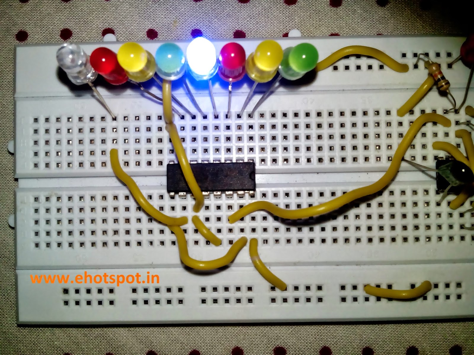
This circuit uses the 555 IC and 4017 IC to flash the LED's one by one placed in shape of a Heart shaped , hence named LED flasher circuit.
The 4017 is a decade counter which flashes the LED's one by one depending upon the clock signal received by it , here 555 produces clock signal and thus drives the 4017 IC to produce output at its pins.
The output LED's can be easily connected in a Heart Shape in order to Make a nice flashing Heart effect.This circuit can be made on a PCB and can be given to your loved ones , thus making it a perfect home made DIY electronic gift for your loved ones.

The speed of flashing can be controlled by the variable resitor , higher the value the slowly LED's will flash and slower the resistance value , the faster the LED's will Flash.
Also the Capacitacnce at pin 2 if 555 can be changed to get particular speed of flashing of LED's.

COMPONENTS REQUIRED :
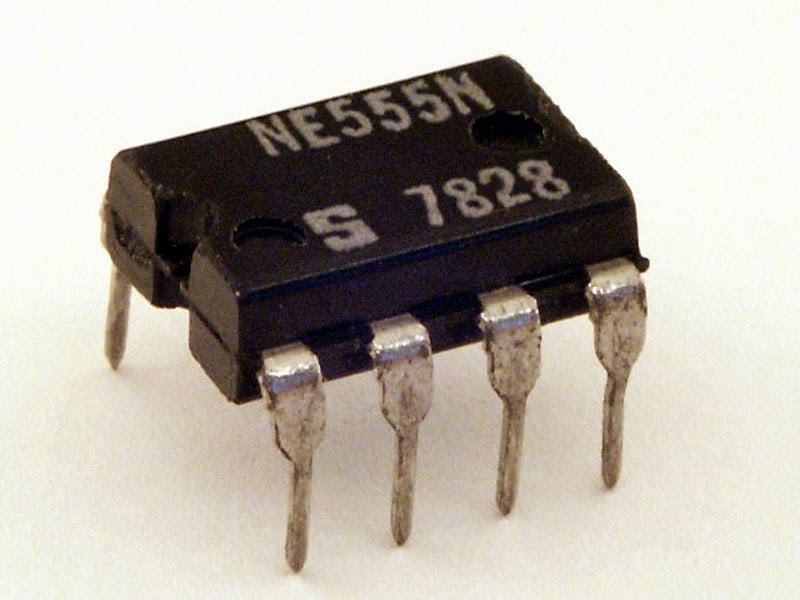
1.one 555 IC
2.one 4017 IC
3.one 100k Resistor
4.one 100k Variable resistor
5.one 1uF Electrolytic capacitance
6.one 220R resistance
7.eight RED LED's
8.one 6-12v supply


Reaction Timer Game with 7 Segment

This is a game for two players. Player 1 presses the START button. This resets the 4026 counter chip and starts the 555 oscillator.
The 555 produces 10 pulses per second and these are counted by the 4026 chip and displayed on the 7-Segment display.
The second player is required to press the STOP button. This freezes the display by activating the Clock Inhibit line of the 4026 (pin 2).
Two time-delay circuits are included. The first activates the 555 by charging a 10u electrolytic and at the same time delivering a (high) pulse to the 4026 chip to reset it. The second timer freezes the count on the display (by raising the voltage on pin 2) so it can be read.


The speed with which the numbers change can be controlled by the capacitor at pin 2 of 555 IC or by changing the resistance between pin 2,3 of  555.
The value of capacitors can be 10uF,1uF,2.2uF and others can also be used but with 10uF the game is easy with 2.2uF its difficult and with 1uF its most difficult as the numbers change very fast so its difficult to stop at particular preselected number.

COMPONENTS USED  :

1.one Common Cathode 7 Segment
2.one 555 IC
3.one 4026 IC
4.two push buttons
5.three 10uF Electrolytic Capacitors
6.three 100k Resistances
7.one 68K Resistance
8.one 1nF Ceramic Capacitor
9.one 6-12v Power supply


CD4060BC DATASHEET

CD4060BC DATASHEET :

CD4049 DATASHEET

CD4049 DATASHEET :

CD4047BC DATASHEET

CD4047BC DATASHEET :

CD4033-2 DATASHEET

CD4033-2 DATASHEET :

CD4027BC DATASHEET

CD4027BC DATASHEET:

CD4017BC DATASHEET

CD4017BC DATASHEET :

CD4015BC DATASHEET

CD4015BC DATASHEET :

CD4001BC DATASHEET

CD4001BC  DATASHEET :

CA3140 DATASHEET

CA3140 DATASHEET :

CA3130 DATASHEET

CA3130 DATASHEET

AD8131 DATASHEET

AD8131 DATASHEET :

SBAS146 Datasheet

SBAS146 Datasheets:

LA4440 Datasheet


Electronic Cricket Match Game using 555 IC and Decade Counter 4017

The Electronic Cricket Match game is presented below, the circuit has 8 LED which represent
 various states in a cricket game - 2 runs ,six ,bowled etc.

When the Push Switch S1 is pressed momentarily, the Astable operates and all the LEDs run very fast sequentially. When S1 is released, any one of the LED stands lit which indicates the status of the match. For example, if LED D7 remains lit, it indicates Sixer and if LED 8 remains lit, it indicates Catch out.
Label each LED for its status as shown in the diagram. Pressing of S1 simulates Bowling and Running LEDs indicates running of Batsman.

 IC1-555 is wired as an Astable Multivibrator with the timing elements R1, R2 and C1. With the shown values of these components very fast output pulses are generated from the Astable. Output from IC1 passes into the input of IC2 which is the popular Johnson Decade counter CD4017. It has 10 outputs. Of these 8 outputs are used. Output 9 ( pin9) is tied to the reset pin 15 to repeat the cycle. When the input pin 14 of IC2 gets low to high pluses, its output turns high one by one. Resistor R3 keeps the input of IC2 low in stand by state to avoid false indications.

COMPONENTS USED :

1.one 555 IC
2.one 4017 IC Decade Counter
3.two 12K resistances
4.one 10K resistance
5.one 100ohm resistance
6.one 1uF Electrolytic Capacitor
7.one 1nF Ceramic capacitor
8.Eight LED (different colors , if possible)
9.one Push Button
10.one 5-12v Supply

 ( NOTE - In Pics below i ommited the 100 ohm Resistor along along LED's as the voltage across LED's was 1.7v so there was no possibility of burning of LED's . Also The value of capacitor on pin 2 of 555 can be changed to higher value of 10uF to decrease the speed of sequential LED flashing when push button is pressed )


555 IC Tester Circuit

This simple 555 IC testing-circuit tests your entire 555 timer IC, so before using your IC check immediately that your IC is good or bad by checking it. This can be done by checking the IC that is it is oscillating or not. Or you can use this circuit in some other circuits also to troubleshoot the proper working of 555 IC.

First of all insert the IC in socket very carefully so that no pin of 555 timer get damage. Now to see the result, switch on the power supply. 
If your 555 timer is working properly, both the LED1 and LED2 will glow.
And any of the LEDs is off or both LED1 and LED2 are not glowing means your 555 timer IC is faulty.


COMPONENTS USED :

  • one 555 IC
  • one 68K Resistance
  • one 39K resistance
  • two 220ohm resistance
  • one 1uF Electrolytic capacitor
  • one 1nf Ceramic capacitor
  • two LED's (any color)


Voltage Doubler Circuit using 555 IC

A voltage higher than the supply can be created by a "Charge-Pump" circuit created with a 555, diodes and capacitors as shown in the following circuit. The output will deliver about 50mA.
This can be used for those components which require around 12v and the supply you have is around 5-6v , thus this is a very handy circuit for electronics DIY projects.


COMPONENTS USED :

1.one 555 IC
2.one 1nF ceramic capacitor
3.one 100nF ceramic capacitor
4.one 33K Resistance
5.two 22uF Electrolytic capacitors
6.two IN4148 Diodes
7.one 5-12V Supply

(NOTE : i have used combination of capacitors to make 22uF )