Electronic Cricket Match Game using 555 IC and Decade Counter 4017
Posted by Rohan on Saturday, August 09, 2014 with 1 comment
The Electronic Cricket Match game is presented below, the circuit has 8 LED which represent
various states in a cricket game - 2 runs ,six ,bowled etc.
When the Push Switch S1 is pressed momentarily, the Astable operates and all the LEDs run very fast sequentially. When S1 is released, any one of the LED stands lit which indicates the status of the match. For example, if LED D7 remains lit, it indicates Sixer and if LED 8 remains lit, it indicates Catch out.
Label each LED for its status as shown in the diagram. Pressing of S1 simulates Bowling and Running LEDs indicates running of Batsman.
 IC1-555 is wired as an Astable Multivibrator with the timing elements R1, R2
and C1. With the shown values of these components very fast output
pulses are generated from the Astable. Output from IC1 passes into the
input of IC2 which is the popular Johnson Decade counter CD4017. It has
10 outputs. Of these 8 outputs are used. Output 9 ( pin9) is tied to the
reset pin 15 to repeat the cycle. When the input pin 14 of IC2 gets low
to high pluses, its output turns high one by one. Resistor R3 keeps the
input of IC2 low in stand by state to avoid false indications.
IC1-555 is wired as an Astable Multivibrator with the timing elements R1, R2
and C1. With the shown values of these components very fast output
pulses are generated from the Astable. Output from IC1 passes into the
input of IC2 which is the popular Johnson Decade counter CD4017. It has
10 outputs. Of these 8 outputs are used. Output 9 ( pin9) is tied to the
reset pin 15 to repeat the cycle. When the input pin 14 of IC2 gets low
to high pluses, its output turns high one by one. Resistor R3 keeps the
input of IC2 low in stand by state to avoid false indications.
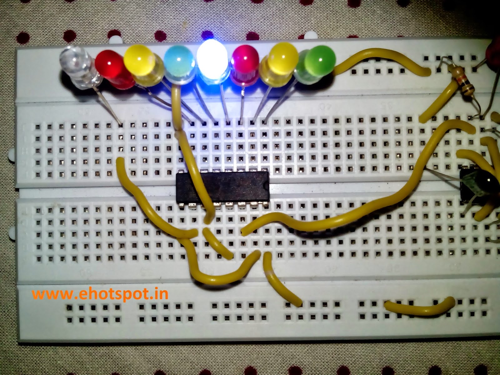
( NOTE - In Pics below i ommited the 100 ohm Resistor along along LED's as the voltage across LED's was 1.7v so there was no possibility of burning of LED's . Also The value of capacitor on pin 2 of 555 can be changed to higher value of 10uF to decrease the speed of sequential LED flashing when push button is pressed )


various states in a cricket game - 2 runs ,six ,bowled etc.
When the Push Switch S1 is pressed momentarily, the Astable operates and all the LEDs run very fast sequentially. When S1 is released, any one of the LED stands lit which indicates the status of the match. For example, if LED D7 remains lit, it indicates Sixer and if LED 8 remains lit, it indicates Catch out.
Label each LED for its status as shown in the diagram. Pressing of S1 simulates Bowling and Running LEDs indicates running of Batsman.
COMPONENTS USED :
1.one 555 IC
2.one 4017 IC Decade Counter
3.two 12K resistances
4.one 10K resistance
5.one 100ohm resistance
6.one 1uF Electrolytic Capacitor
7.one 1nF Ceramic capacitor
8.Eight LED (different colors , if possible)
9.one Push Button
10.one 5-12v Supply
( NOTE - In Pics below i ommited the 100 ohm Resistor along along LED's as the voltage across LED's was 1.7v so there was no possibility of burning of LED's . Also The value of capacitor on pin 2 of 555 can be changed to higher value of 10uF to decrease the speed of sequential LED flashing when push button is pressed )


where we can use this technology.i mean applications.
ReplyDelete